

Nitrogen Generator for Electronics Manufacturing in China
Project Overview
Huatai supplied a KFD49-50 nitrogen generation system to Chengdu Ruidiwei Technology Co., Ltd. for nitrogen blanketing of product storage cabinets. The fixed rooftop system was configured for continuous operation and delivers 50 Nm³/h of nitrogen at ≥99.99% purity, with an adjustable delivery pressure of 0–0.5 MPa.
Following system commissioning and acceptance, Huatai provided operational training for the customer’s personnel. According to the available project record, the system has remained in operation for more than one year.
- Application: Nitrogen blanketing for product storage cabinets
- Nitrogen Generator: KFD49-50
- Nitrogen Flow: 50 Nm³/h
- Nitrogen Purity: ≥99.99%
- Delivery Pressure: 0–0.5 MPa
- Installation: Fixed outdoor rooftop system
Need some help?
If you are unsure exactly what you need,
get in touch and we can help identify your requirements.
What Nitrogen Supply Did the Electronics Project Require?
 Chengdu Ruidiwei Technology Co., Ltd. required a dedicated nitrogen supply for product cabinet blanketing on a new production line. As no existing nitrogen source was available, the customer needed an on-site nitrogen generation system configured for continuous operation.
The system configuration was based on three confirmed requirements: nitrogen purity of ≥99.99%, a flow rate of 50 Nm³/h and an adjustable delivery pressure of 0–0.5 MPa.
Nitrogen Requirements
- Purity: ≥99.99%
- Purity: ≥99.99%
- Flow: 50 Nm³/h
- Delivery Pressure: 0–0.5 MPa
- Delivery Pressure: 0–0.5 MPa
- Operating Mode: Continuous
- Power Supply: 380/220 V
- Control System: Siemens PLC
Huatai configures nitrogen generators for electronics manufacturing according to the specific application, required purity, flow rate, pressure and operating schedule.
How Was the Rooftop Nitrogen System Configured?
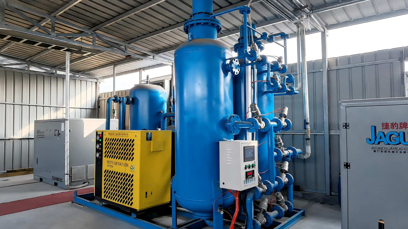
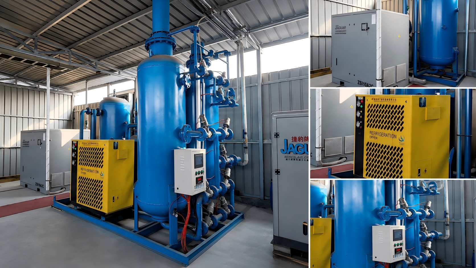
Huatai configured a complete on-site nitrogen generation system for fixed outdoor installation on the roof of the customer’s office building. The rooftop location provided open ventilation around the equipment, while the layout retained access for operation, inspection and routine maintenance.
The system included:
- 1. Screw air compressor
- 2. Air receiver tank
- 3. Refrigerated air dryer
- 4. Three-stage filtration system
- 5. KFD49-50 nitrogen generator
- 6. Nitrogen receiver tank
- 7. Siemens PLC control system
Nitrogen Supply Process
Ambient Air → Screw Air Compressor → Air Receiver Tank → Refrigerated Air Dryer → Three-Stage Filtration → KFD49-50 Nitrogen Generator → Nitrogen Receiver Tank → Product Cabinets
Compressed air is stored, dried and filtered before entering the nitrogen generator. The generated nitrogen is then collected in the nitrogen receiver tank and supplied through the pipeline to the customer’s product cabinets.
Automatic Control
The Siemens PLC manages the programmed operating sequence and valve switching. During normal operation, the nitrogen generator completes each operating cycle according to the configured control logic.
The rooftop system still requires routine inspection, operating-parameter checks and scheduled maintenance. It should not be treated as a completely unattended installation.
Rooftop Installation Review
For a rooftop nitrogen generation system, the following conditions should be reviewed during project planning:
- Roof load capacity and equipment foundation
- Weather protection and drainage
- Ventilation around the equipment
- Power supply conditions
- Nitrogen pipeline route to the point of use
- Noise and vibration control
- Operating and maintenance clearance
- Equipment lifting and delivery route
- Applicable lightning and electrical protection
In this project, open ventilation around the installed equipment was available. Roof loading, weather protection, lightning protection and vibration-control conditions should only be stated as confirmed project results when the relevant site or engineering documents are available.
How Was the System Connected to the Product Cabinets?
After generation, the nitrogen is buffered in the nitrogen receiver tank and delivered to the customer’s product cabinets through the project’s downstream nitrogen distribution system.
At the supply side, the system was configured for the required nitrogen purity, flow rate and delivery pressure. The pressure and flow available at each cabinet also depend on the downstream pipe length, branch arrangement, simultaneous gas demand and cabinet operating conditions.
For similar projects, the following information should be confirmed before final system and pipeline design:
- Number of product cabinets
- Nitrogen demand per cabinet
- Simultaneous operating demand
- Required pressure at each cabinet
- Main pipeline length
- Branch pipeline arrangement
- Distance from the rooftop system to the point of use
- Point-of-use pressure, flow and purity monitoring
- Allowance for future cabinet expansion
The final distribution layout, branch flow rates and monitoring requirements should be reviewed against the customer’s cabinet configuration and actual production conditions.
Huatai develops complete Gas Generation Solutions covering compressed-air supply, air treatment, gas separation, storage and automatic control.
Commissioning, Acceptance and Operator Training
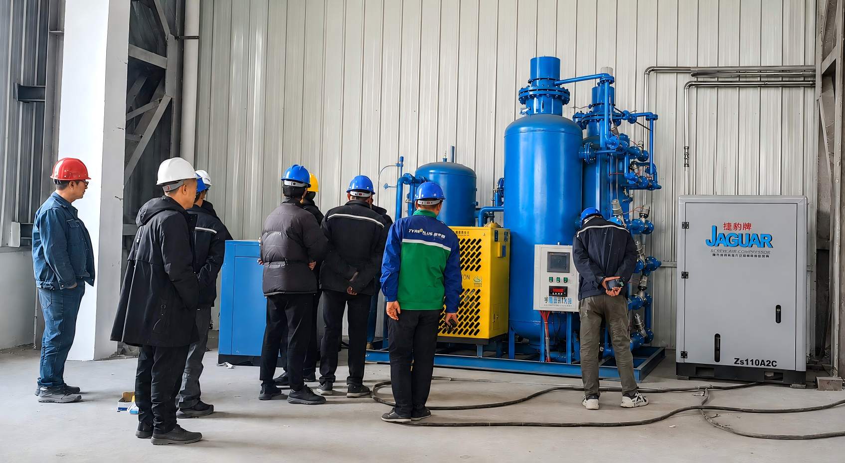
After system commissioning and acceptance, Huatai provided on-site operating training for the customer’s personnel. The training covered the installed system configuration, normal operating procedures and routine equipment checks.
The training included:
- Identification of the main system components
- Normal start and stop procedures
- Siemens PLC interface operation
- Basic operating-parameter checks
- Routine inspection points
- Applicable maintenance reminders
The project images document the operator training conducted beside the installed rooftop nitrogen generation system. Training and commissioning records, acceptance documents or service reports may also be provided for project review when available.
Operating Record After More Than One Year
The KFD49-50 nitrogen generation system was installed and commissioned to supply nitrogen to the customer’s product cabinets. According to the available project record, the system has been in operation for more than one year.
The completed system was configured for:
- Nitrogen flow rate: 50 Nm³/h
- Nitrogen purity: ≥99.99%
- Supply pressure: 0–0.5 MPa
- Application: Nitrogen supply for product cabinets
- Installation: Fixed rooftop installation
- Operating mode: Continuous operation configuration
Commissioning, acceptance and operator training were completed after installation. This project provides a practical reference for electronics manufacturers evaluating an on-site nitrogen system with similar flow, purity, pressure and rooftop installation requirements.
“More than one year in operation” describes the recorded operating period; it does not imply uninterrupted operation or performance beyond the available project data.
Rooftop projects require a review of the applicable nitrogen generator installation requirements, including equipment layout, foundation, access, power, pipe routing and environmental protection.
What Should Buyers Confirm for a Similar Project?
| Project Information | What to Confirm |
| Cabinet Application | Products stored or protected inside the cabinets |
| Cabinet Quantity | Total cabinet quantity and number operating simultaneously |
| Nitrogen Purity | Required purity at the main supply point and point of use |
| Nitrogen Flow | Normal consumption and estimated peak demand |
| Delivery Pressure | Required main-line and cabinet inlet pressure |
| Pipe Route | Pipeline distance, height difference and branch arrangement |
| Installation Area | Rooftop, equipment room or production area |
| Operating Schedule | Daily operating hours or continuous operation |
| Site Utilities | Available power supply and compressed-air conditions |
| Site Conditions | Ventilation, drainage, access and maintenance clearance |
| Future Demand | Planned cabinet additions or production expansion |